_x000D_
By Harry Valentine 2019-10-05 22:50:47
_x000D_
_x000D_
Many technical innovations developed in the aeronautical industry have successfully been adapted maritime application. Several years ago, a model airplane builder installed transverse axis, cylindrical paddle wheels into the top sides of airplane wings to allow for extremely low flight speeds. Adapting that innovation to maritime application offers the promise of improving hydrofoil performance, airfoil-sail performance, boat rudder performance and kinetic ferry propulsive performance.
_x000D_
_x000D_
Introduction
_x000D_
_x000D_
It is possible in transportation history that innovations first developed in the maritime sector might have influenced the developments of early man-made sustained flight, involving kites in China. Early Chinese wind-powered boats used sails made from wooden slats, while wind-driven sailing vessels developed elsewhere used sails made from woven fabric such as help. Innovations in the development of looms contributed to increasing the supply of woven fabric, including fabric made of very fine thread such as silk. The frames of early silk fabric kites resembled the mast and stay above decks of sailing ships.
_x000D_
_x000D_
Development and advances in kite designs capable of lifting increased weight formed the basis of early airplane wing development. By the latter 20th century, a few boat builders adapted airplane wing profiles to wind-driven sail boats to increase sailing speed. Adapting airplane wing profile below the water surface provides the basis for further hydrofoil vessel development, improved kinetic ferry propulsion and improved rudder performance, by increasing the dynamic pressure difference between the upstream and downstream sides of these components. A recent aeronautical innovation offers the potential to further increase the pressure difference.
_x000D_
_x000D_
Paddle Wheel on Wing
_x000D_
_x000D_
A hobbyist installed a transverse-axis paddle wheel into the top side of wings attached to a powered scale-model aircraft. While the paddle-cylinder propelled the aircraft forward, it allowed the wing rear flap to point down at an extreme angle, with the air stream remaining in contact with the flap upper surface. By comparison, conventional wings would undergo the phenomena called “stall” and resulting in the aircraft falling toward ground. Other airplane model builders have combined conventional propeller propulsion with airstream activated rotating cylinders installed into the upper side of the wings.
_x000D_
_x000D_
While in flight, the rotating cylinders allow the wing rear flaps to be adjusted to beyond the stall angle on a conventional model airplane. Each rotating cylinder redirected the airstream boundary layer to remain in contact with the steeply angled flap and allowing for low speed flight. Pairs of wind-activated counter-rotating cylinders would have possible application above the deck of a wind-powered ship while water-stream activated rotating cylinders could have future application being designed into future hydrofoils. The concept may also have application on boat rudders as well as propulsion rudders applied to water-current propelled kinetic ferry vessels.
_x000D_
_x000D_
_x000D_
_x000D_
Twin Rotor and Airfoil-Sail
_x000D_
_x000D_
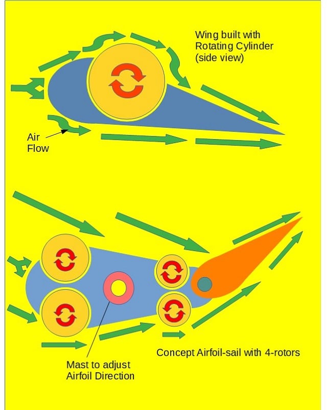
Sails, airfoil-sails and wind activated Magnus rotors are well proven in maritime propulsion. Airfoils that function as boat sails represent aeronautical design precedent adapted to maritime application. The paddle-wheel-in wing concept provides a basis to install small-diameter Magnus rotors into each side of an airfoil-sail, to direct a wind stream over the shadow side surface while the airfoil-sail would be adjusted to an extreme angle. Wind blowing on a conventional sail’s upstream side slightly increases dynamic pressure while simultaneously reducing air pressure zone on shadow side. The difference in air pressure between the sides of the sail produces propulsion.
_x000D_
_x000D_
A rotating cylinder redirecting a wind stream over the shadow side of an airfoil-sail offers the potential to further reduce the air pressure on the sail’s shadow side, increasing the difference in pressure between upstream and downstream sides and potentially increasing propulsive force. Aeronautical innovation provides the precedent for such a result, with potential to either increase wind-powered vessel sailing speed or to enable the vessel to de designed to sail with heavier payload. Ship and boat designers may undertake further innovative research into combining foil-sails with twin vertical-axis counter-rotating cylinders to enhance wind-powered vessel propulsion.
_x000D_
_x000D_
Winglets
_x000D_
_x000D_
To improve aeronautical wing performance, the aeronautical sector has attached winglets to wing tips on large aircraft and also on ground effect vehicles to redirect a wind flow that would otherwise reduce lift and increase drag. Adding horizontal winglets to the tops of airfoil-sails built with vertical-axis counter-rotating cylinders would redirect the air stream that usually flows over the top of sails and into the low-pressure zone on the downwind side of the sail. Winglets would slightly increase the difference in air pressure between upstream and downstream sides of the rotating-cylinder airfoil-sails, increasing propulsive force.
_x000D_
_x000D_
Adapting rotating cylinders and horizontal winglets to airfoil-sails offers the option of adding a hinge, to produce a compound two-section airfoil-sail built with two pairs of counter-rotating cylinders. Prevailing wind would drive the micro-turbines mounted on top of all four cylinders to produce rotation. On the shadow side of the airfoil-sail, the leading cylinder would redirect the wind stream through an angle and over the shadow side surface of the forward section of airfoil-sail, followed by the trailing rotating cylinder redirecting the wind stream through a second angle and over the shadow side surface of the trailing airfoil-sail.
_x000D_
_x000D_
Kite Sails
_x000D_
_x000D_
In recent years and courtesy of new generation high-strength, lightweight textile fiber along with developments in innovative frameless kite design, kites have again been adapted to boat propulsion and accessing higher-speed wind that blows at higher elevation. During earlier times dating back into the mid-19th century, kite designers and builders developed lifting kites capable of carrying a human observer such as a surveyor to higher elevation. In regions where trade winds blow, high-flying supersize frameless kites replace sails and use high-strength lightweight tethers to pull boats and even assist in ship propulsion to reduce fuel consumption.
_x000D_
_x000D_
One developer of airborne wind power technology used an air-filled, transverse-axis rotating cylinder to drive an airborne electric generator. The lightweight rotating cylinder can also be adapted to redirect part of the high-elevation wind stream to the kite-sail downstream side, reducing air pressure in the low-pressure zone and increasing the pressure difference between the upstream and downstream sides. Such dynamic offers the potential of increasing the pull on the tether, either allowing the boat to sail at higher speed or allowing wind energy to propel a heavier boat. It is a concept requiring further research in the future.
_x000D_
_x000D_
Hydrofoils
_x000D_
_x000D_
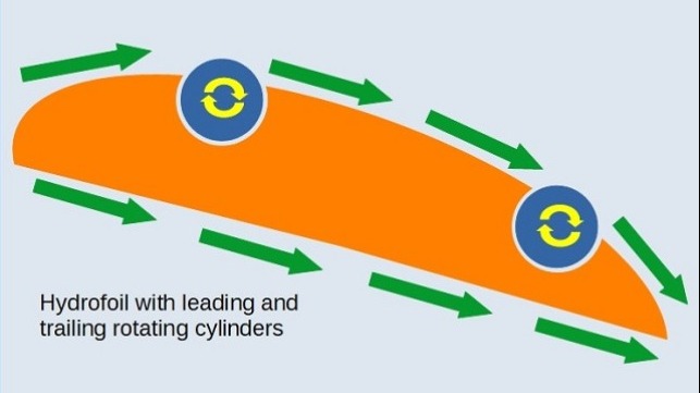
Hydrofoils built with a water current driven rotating cylinder on the upper side would redirect the water boundary layer to flow over a more steeply downward angled rear section, than if the cylinder were absent. Such a hydrofoil would offer greater upward lift at lower sailing speed, allowing for smoother low speed sailing through choppy water or allowing it to carry additional weight when sailing at higher speed. Presently, some small hydrofoil taxi vessels transition to hydrofoil sailing at nine knots. A rotating cylinder built into a modified hydrofoil could likely transition to hydrofoil sailing at between five and seven knots.
_x000D_
_x000D_
Large commercial service hydrofoil vessels are restricted to maximum 400 tonnes weight due to squared increase in “wing” area being outmatched by simultaneous cubed increase in vessel tonnage. Further research would determine the percentage tonnage increase that rotating cylinder hydrofoil technology could offer to large hydrofoil vessels. A compound two-section hydrofoil would use forward and trailing current-driven rotating cylinders built into leading areas of each of the hydrofoil upper surfaces. An extended length vessel equipped with such hydrofoil technology would likely sail very smoothly with minimal pitch and roll, at low speed through choppy water surface.
_x000D_
_x000D_
 GMC Assistant